实现位图数据的叠加
1.叠加效果
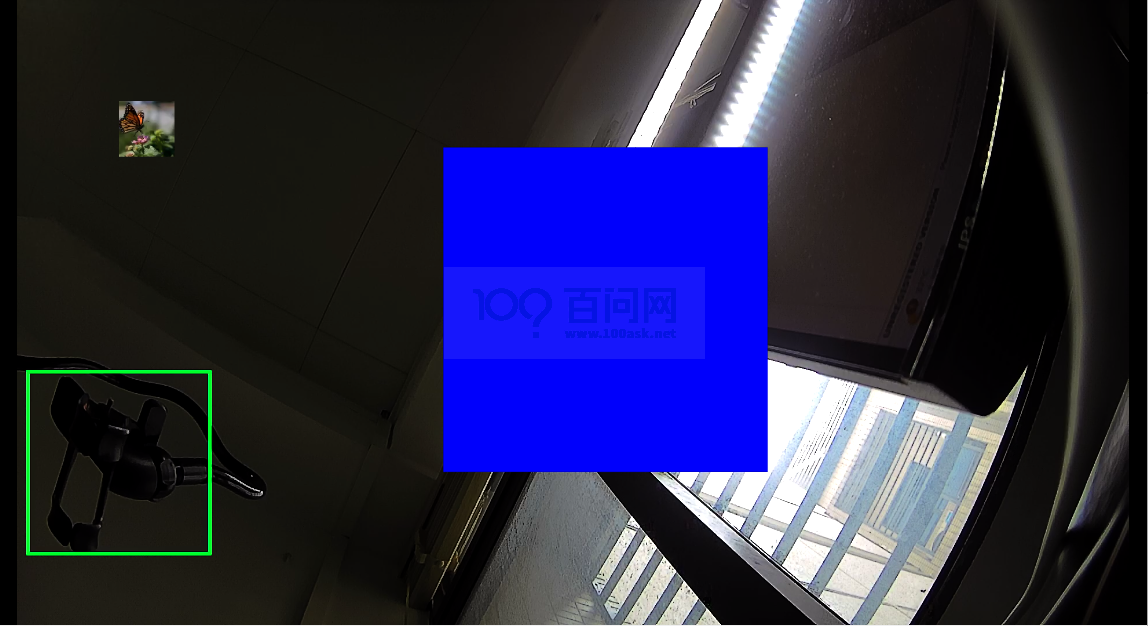
前面我们使用overlay方式叠加纯色数据至编码通道中,这一小节我们将图片数据叠加至编码通道中,效果如下所示:

可以看到原来的红色框变成了一张图像。
2.实现步骤
我们在前面介绍中,overlay的区域叠加类型是支持位图加载的,所以我们只需要准备图像/文字的位图数据传入叠加模块即可。
2.1 准备bmp图像位图
在开始前,请注意:图像的尺寸大小需要遵循16对齐,即宽高的值需要为16的倍数。

这里我提前准备了一张96*96分辨率,32位深的BMP图像,使用下面的程序,将图像转换为位图数据。
#include <stdio.h>
#include <stdlib.h>
#include <string.h>

#pragma pack(1) // 确保结构体按1字节对齐

// 定义位图文件头结构体
typedef struct {
    unsigned short bfType;       // 文件类型,必须是0x4D42,即'BM'
    unsigned int bfSize;         // 文件大小,以字节为单位
    unsigned short bfReserved1;  // 保留,必须为0
    unsigned short bfReserved2;  // 保留,必须为0
    unsigned int bfOffBits;      // 从文件头到实际图像数据的偏移量,以字节为单位
} BITMAPFILEHEADER;

// 定义位图信息头结构体
typedef struct {
    unsigned int biSize;         // 信息头大小,以字节为单位
    int biWidth;                 // 图像宽度,以像素为单位
    int biHeight;                // 图像高度,以像素为单位
    unsigned short biPlanes;     // 颜色平面数,必须为1
    unsigned short biBitCount;   // 每像素位数,常见值为1、4、8、16、24、32
    unsigned int biCompression;  // 压缩类型
    unsigned int biSizeImage;    // 图像大小,以字节为单位
    int biXPelsPerMeter;         // 水平分辨率,每米像素数
    int biYPelsPerMeter;         // 垂直分辨率,每米像素数
    unsigned int biClrUsed;      // 实际使用的颜色数
    unsigned int biClrImportant; // 重要颜色数
} BITMAPINFOHEADER;

// 定义RGB四元组结构体,用于32位深度的图像
typedef struct {
    unsigned char rgbBlue;       // 蓝色分量
    unsigned char rgbGreen;      // 绿色分量
    unsigned char rgbRed;        // 红色分量
    unsigned char rgbReserved;   // 保留字节
} RGBQUAD;

// 垂直翻转图像数据的函数
void flipVertical(RGBQUAD *imageData, int width, int height) {
    int rowSize = width * sizeof(RGBQUAD); // 每行的字节数
    RGBQUAD *tempRow = (RGBQUAD *)malloc(rowSize); // 临时行缓冲区

    for (int y = 0; y < height / 2; y++) {
        // 交换第y行和倒数第y行
        memcpy(tempRow, &imageData[y * width], rowSize);
        memcpy(&imageData[y * width], &imageData[(height - 1 - y) * width], rowSize);
        memcpy(&imageData[(height - 1 - y) * width], tempRow, rowSize);
    }

    free(tempRow); // 释放临时行缓冲区
}

int main() {
    FILE *bmpFile = fopen("input.bmp", "rb"); // 打开BMP文件
    if (!bmpFile) {
        printf("无法打开BMP文件\n");
        return 1;
    }

    BITMAPFILEHEADER fileHeader;
    fread(&fileHeader, sizeof(BITMAPFILEHEADER), 1, bmpFile); // 读取文件头

    if (fileHeader.bfType != 0x4D42) { // 检查文件类型
        printf("不是有效的BMP文件\n");
        fclose(bmpFile);
        return 1;
    }

    BITMAPINFOHEADER infoHeader;
    fread(&infoHeader, sizeof(BITMAPINFOHEADER), 1, bmpFile); // 读取信息头

    // 修改分辨率和位深
    infoHeader.biWidth = 96;
    infoHeader.biHeight = 96;
    infoHeader.biBitCount = 32;
    infoHeader.biSizeImage = infoHeader.biWidth * abs(infoHeader.biHeight) * (infoHeader.biBitCount / 8);

    RGBQUAD *imageData = (RGBQUAD *)malloc(infoHeader.biSizeImage); // 分配图像数据内存
    fseek(bmpFile, fileHeader.bfOffBits, SEEK_SET); // 移动文件指针到图像数据开始位置
    fread(imageData, infoHeader.biSizeImage, 1, bmpFile); // 读取图像数据
    fclose(bmpFile); // 关闭文件

    // 上下翻转图像数据
    flipVertical(imageData, infoHeader.biWidth, abs(infoHeader.biHeight));

    FILE *osdFile = fopen("osd.file", "wb"); // 创建输出文件
    if (!osdFile) {
        printf("无法创建OSD文件\n");
        free(imageData);
        return 1;
    }

    // 写入图像数据到osd.file
    fwrite(imageData, infoHeader.biSizeImage, 1, osdFile);
    fclose(osdFile); // 关闭输出文件

    free(imageData); // 释放图像数据内存
    printf("位图数据已成功保存到osd.file文件中\n");
    return 0;
}
读取一个BMP格式的图像文件,将其图像数据进行垂直翻转,然后将翻转后的图像数据保存到一个新的文件中。
2.2 修改源码
将源码中填充位图数据的函数,修改成从文件中读取位图数据,即读取前面生成的bmp图像位图数据。
static void GenerateARGB8888(void* pBuf, int nSize)
{
    unsigned int nA0Color = 0x80FF0000;
    unsigned int nA1Color = 0xFFFF0000;
    unsigned int *pInt = (unsigned int*)pBuf;
    int i = 0;
 /*
    for(i=0; i< nSize/8; i++)
    {
        *pInt = nA0Color;
        pInt++;
    }
    for(i=0; i< nSize/8; i++)
    {
        *pInt = nA1Color;
        pInt++;
    }
    */
    #if 1
    FILE* pOsdFile = fopen("/tmp/osd.file", "rb");
    int nRdBytes = fread(pBuf, 1, nSize, pOsdFile);
    if(nRdBytes != nSize)
    {
        aloge("fatal error! read argb8888 osd file wrong!%d!=%d", nRdBytes, nSize);
    }
    fclose(pOsdFile);
#endif
}
2.1 修改配置文件
修改配置文件中overlay的宽高,此宽高必须和叠加的位图数据宽高一致。
# set overlay_w or overlay_h is 0 means disable overlay test.
overlay_x = 16
overlay_y = 16
overlay_w = 96
overlay_h = 96
3.总结
- 初始化环境:
- 配置和初始化全志芯片的环境,包括加载必要的驱动和库。
- 创建区域(Region):
- 使用
AW_MPI_RGN_Create函数创建一个区域。区域可以是Overlay(叠加)、Cover(遮挡)等类型。
- 使用
- 加载位图或文字:
- 对于图像,可以使用
AW_MPI_RGN_SetBitMap函数将位图数据加载到区域中。 - 对于文字,也是类似生成位图,然后加载到区域中。
- 对于图像,可以使用
- 设置通道显示属性:
- 配置区域在通道中的显示属性,如位置、透明度、层次等。
- 将区域附加到通道:
- 使用
AW_MPI_RGN_AttachToChn函数将创建的区域附加到指定的通道(如VENC通道)上。
- 使用