28BYJ-48步进电机驱动
介绍
参考《HAL快速入门与项目实战(基于DshanMCU-F407)_V1.0》
参考 步进电机
参考 步进电机原理
步进电机控制特点:
- 它是通过输入脉冲信号来进行控制的。
- 电机的总转动角度由输入脉冲数决定。
- 电机的转速由脉冲信号频率决定。
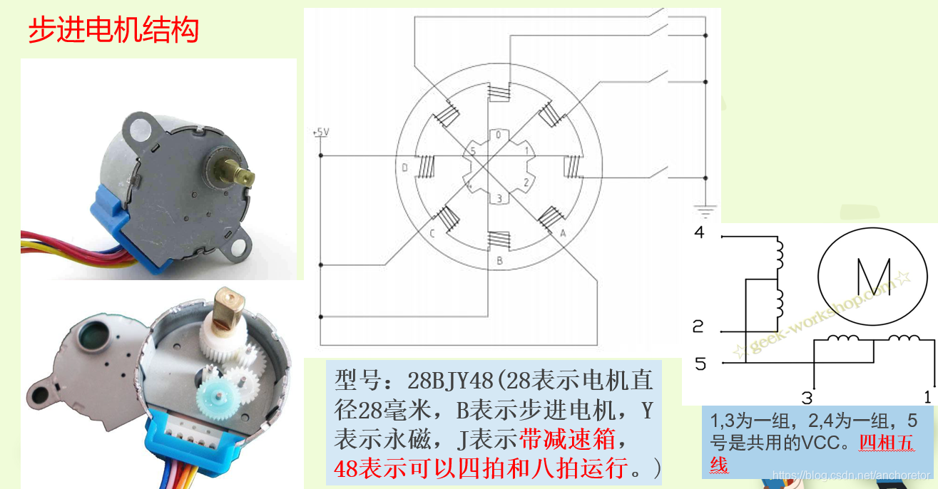
步进电机结构
步进电机控制的基本概念
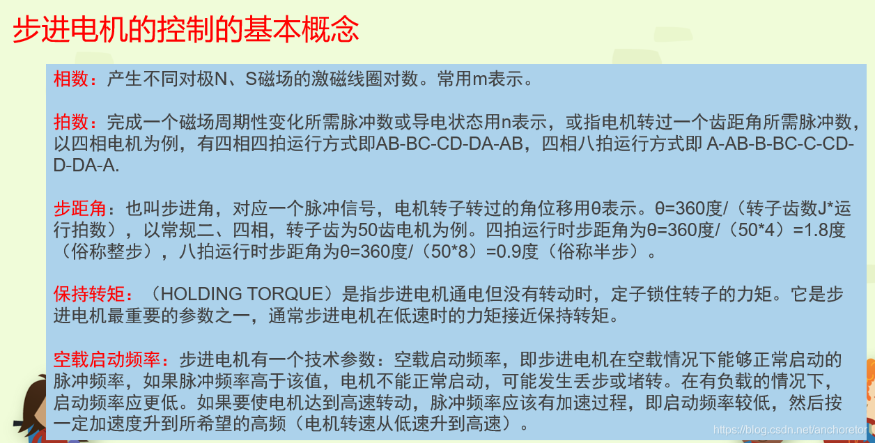
步进电机驱动拍数设置
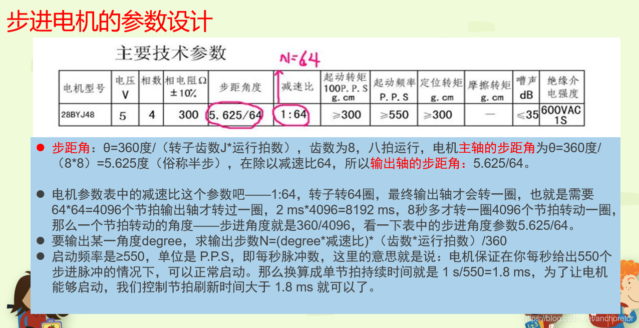
步进电机驱动参数设置
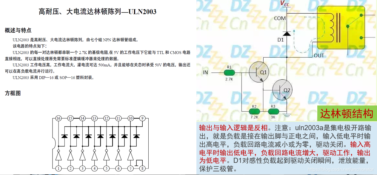
ULN2003驱动电路
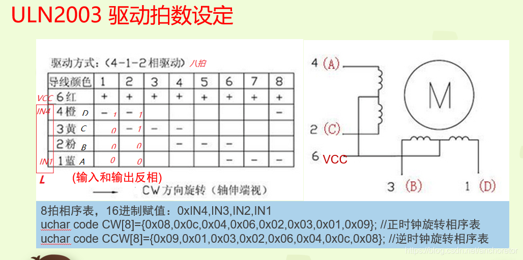
ULN2003驱动拍数设定

步进电机驱动程序
假设读者已有STM32定时器和PWM的相关概念
driver_28BYJ_48.h
#ifndef __DRIVER_28BYJ_48_H__
#define __DRIVER_28BYJ_48_H__

#ifdef __cplusplus
extern "C" {
#endif

typedef enum
{
    STEP_MODE_HALF = 0x00,
    STEP_MODE_FULL = 0x01
} motor_step_mode_t;

uint8_t a_28byj_48_init(TIM_HandleTypeDef *tim_handle);

uint8_t a_28byj_48_rotate(motor_step_mode_t step_mode, uint16_t time_delay_us, uint8_t direction);

uint8_t a_28byj_48_rotation_clockwise(motor_step_mode_t step_mode, uint16_t speed);

uint8_t a_28byj_48_rotation_counterclockwise(motor_step_mode_t step_mode, uint16_t time_delay_us);

void a_28byj_48_continuous_rotation(motor_step_mode_t step_mode, float speed_rpm, uint8_t direction);

uint8_t a_28byj_48_stop(void);

void a_28byj_48_toggle_direction(uint8_t *current_direction);

uint8_t a_28byj_48_position_control(motor_step_mode_t step_mode, int32_t target_position, int32_t *current_position, uint16_t time_delay_us);

void a_28byj_48_lock_position(void);

uint16_t a_28byj_48_set_speed(motor_step_mode_t step_mode, float speed_rpm);

uint8_t a_28byj_48_step_angle(motor_step_mode_t step_mode, float angle, uint8_t direction);

uint8_t a_28byj_48_microstep_drive(motor_step_mode_t step_mode, uint16_t microstep_count, uint16_t time_delay_us, uint8_t direction);

uint8_t a_28byj_48_accel_decel_drive(motor_step_mode_t step_mode, uint16_t total_steps, float max_speed_rpm, uint16_t acceleration, uint16_t deceleration, uint8_t direction);

#ifdef __cplusplus
}
#endif

#endif
driver_28BYJ_48.c
#include "driver_28BYJ_48.h"
#include "delay.h"

/* Timer handle and GPIO definitions */
static TIM_HandleTypeDef a_28byj_48_tim_handle;

#define MOTOR_28BYJ_48_IN1 TIM_CHANNEL_1
#define MOTOR_28BYJ_48_IN2 TIM_CHANNEL_2
#define MOTOR_28BYJ_48_IN3 TIM_CHANNEL_3
#define MOTOR_28BYJ_48_IN4 TIM_CHANNEL_4

#define MOTOR_28BYJ_48_GPIO_Port GPIOD
#define MOTOR_28BYJ_48_GPIO_Pin_IN1 GPIO_PIN_12
#define MOTOR_28BYJ_48_GPIO_Pin_IN2 GPIO_PIN_13
#define MOTOR_28BYJ_48_GPIO_Pin_IN3 GPIO_PIN_14
#define MOTOR_28BYJ_48_GPIO_Pin_IN4 GPIO_PIN_15

uint8_t current_step = 0;

/* Step sequences */
const uint8_t step_sequence_full[4] = {
    0x01, /* 0b0001 IN1 */
    0x02, /* 0b0010 IN2 */
    0x04, /* 0b0100 IN3 */
    0x08  /* 0b1000 IN4 */
};

const uint8_t step_sequence_half[8] = {
    0x01, /* 0b0001 IN1 */
    0x03, /* 0b0011 IN1 + IN2 */
    0x02, /* 0b0010 IN2 */
    0x06, /* 0b0110 IN2 + IN3 */
    0x04, /* 0b0100 IN3 */
    0x0C, /* 0b1100 IN3 + IN4 */
    0x08, /* 0b1000 IN4 */
    0x09  /* 0b1001 IN4 + IN1 */
};

/* Initialization */
uint8_t a_28byj_48_init(TIM_HandleTypeDef *tim_handle) {
    a_28byj_48_tim_handle = *tim_handle;
    TIM_OC_InitTypeDef sConfig = {0};

    /* Configure timer for 1 MHz frequency */
    a_28byj_48_tim_handle.Init.Prescaler = (SystemCoreClock / 1000000) - 1;
    a_28byj_48_tim_handle.Init.CounterMode = TIM_COUNTERMODE_UP;
    a_28byj_48_tim_handle.Init.Period = 100 - 1; /* 10 kHz PWM frequency */
    a_28byj_48_tim_handle.Init.ClockDivision = TIM_CLOCKDIVISION_DIV1;
    a_28byj_48_tim_handle.Init.AutoReloadPreload = TIM_AUTORELOAD_PRELOAD_ENABLE;
    if (HAL_TIM_PWM_Init(&a_28byj_48_tim_handle) != HAL_OK) {
        return 1; /* Initialization failed */
    }

    sConfig.OCMode = TIM_OCMODE_PWM1;
    sConfig.Pulse = 0; /* Default off */
    sConfig.OCPolarity = TIM_OCPOLARITY_HIGH;
    sConfig.OCFastMode = TIM_OCFAST_ENABLE;

    if (HAL_TIM_PWM_ConfigChannel(&a_28byj_48_tim_handle, &sConfig, MOTOR_28BYJ_48_IN1) != HAL_OK ||
        HAL_TIM_PWM_ConfigChannel(&a_28byj_48_tim_handle, &sConfig, MOTOR_28BYJ_48_IN2) != HAL_OK ||
        HAL_TIM_PWM_ConfigChannel(&a_28byj_48_tim_handle, &sConfig, MOTOR_28BYJ_48_IN3) != HAL_OK ||
        HAL_TIM_PWM_ConfigChannel(&a_28byj_48_tim_handle, &sConfig, MOTOR_28BYJ_48_IN4) != HAL_OK) {
        return 2; /* Channel configuration failed */
    }

    HAL_TIM_PWM_Start(&a_28byj_48_tim_handle, MOTOR_28BYJ_48_IN1);
    HAL_TIM_PWM_Start(&a_28byj_48_tim_handle, MOTOR_28BYJ_48_IN2);
    HAL_TIM_PWM_Start(&a_28byj_48_tim_handle, MOTOR_28BYJ_48_IN3);
    HAL_TIM_PWM_Start(&a_28byj_48_tim_handle, MOTOR_28BYJ_48_IN4);

    return 0; /* Initialization success */
}

/* Update PWM signals for motor control */
void a_28byj_48_update_pwm(uint8_t step_value, uint16_t speed)
{
    __HAL_TIM_SET_COMPARE(&a_28byj_48_tim_handle, MOTOR_28BYJ_48_IN1, (step_value & 0x01) ? speed : 0);
    __HAL_TIM_SET_COMPARE(&a_28byj_48_tim_handle, MOTOR_28BYJ_48_IN2, (step_value & 0x02) ? speed : 0);
    __HAL_TIM_SET_COMPARE(&a_28byj_48_tim_handle, MOTOR_28BYJ_48_IN3, (step_value & 0x04) ? speed : 0);
    __HAL_TIM_SET_COMPARE(&a_28byj_48_tim_handle, MOTOR_28BYJ_48_IN4, (step_value & 0x08) ? speed : 0);
}

/* Stop the motor */
uint8_t a_28byj_48_stop(void)
{
    /* Set all PWM outputs to 0 to stop the motor */
    __HAL_TIM_SET_COMPARE(&a_28byj_48_tim_handle, MOTOR_28BYJ_48_IN1, 0);
    __HAL_TIM_SET_COMPARE(&a_28byj_48_tim_handle, MOTOR_28BYJ_48_IN2, 0);
    __HAL_TIM_SET_COMPARE(&a_28byj_48_tim_handle, MOTOR_28BYJ_48_IN3, 0);
    __HAL_TIM_SET_COMPARE(&a_28byj_48_tim_handle, MOTOR_28BYJ_48_IN4, 0);

    return 0;
}

/* Rotate the motor */
uint8_t a_28byj_48_rotate(motor_step_mode_t step_mode, uint16_t time_delay_us, uint8_t direction)
{
    const uint8_t *step_sequence = step_mode == STEP_MODE_HALF ? step_sequence_half : step_sequence_full;
    uint8_t step_count = step_mode == STEP_MODE_HALF ? 8 : 4;

    if (direction) {
        current_step = (current_step + 1) % step_count; /* Clockwise */
    } else {
        current_step = (current_step - 1 + step_count) % step_count; /* Counterclockwise */
    }

    uint8_t step_value = step_sequence[current_step];
    a_28byj_48_update_pwm(step_value, 100);

    /* Clamp delay between 560 and 9000 us */
    time_delay_us = (time_delay_us < 560) ? 560 : (time_delay_us > 9000 ? 9000 : time_delay_us);

    delay_us(time_delay_us);

    return 0;
}

/* Lock the motor at the current position */
void a_28byj_48_lock_position(void)
{
    uint8_t step_value = current_step < 4 ? step_sequence_full[current_step] : step_sequence_half[current_step];
    a_28byj_48_update_pwm(step_value, 100);
}

/**
 * a_28byj_48_set_speed
 * Set the speed of the motor by adjusting the delay between steps.
 *
 * @param step_mode: The step mode (STEP_MODE_FULL or STEP_MODE_HALF).
 * @param speed_rpm: Desired speed in revolutions per minute (RPM).
 *
 * @return time_delay_us: Computed delay in microseconds for the desired speed.
 *
 * 通过参数 RPM 来设置目标转速(转/分钟),通过目标转速计算出不同步进模式下,每步需要的时间
 *
 * 每步延时的时间(每步的目标时间 ,微秒)= 每分钟的微秒数 / 每分钟的步数 = (60 * 10^6) / (RPM * 每圈步数)
 */
uint16_t a_28byj_48_set_speed(motor_step_mode_t step_mode, float speed_rpm)
{
    float steps_per_revolution = step_mode == STEP_MODE_HALF ? 4096.0 : 2048.0;
    uint16_t time_delay_us = (uint16_t)((60.0 * 1000000.0) / (speed_rpm * steps_per_revolution));

    if (time_delay_us < 560) {
        time_delay_us = 560;
    } else if (time_delay_us > 9000) {
        time_delay_us = 9000;
    }

    return time_delay_us;
}

/**
 * a_28byj_48_step_angle
 * Rotate the motor by a specific angle.
 *
 * @param step_mode: The step mode (STEP_MODE_FULL or STEP_MODE_HALF).
 * @param angle: The angle to rotate in degrees.
 * @param direction: Direction of rotation (1 for clockwise, 0 for counterclockwise).
 *
 * @return 0 if successful, 1 if an error occurs.
 *
 * 28BYJ-48 是4相8拍步进电机,其内部结构决定了步进电机内部转子每步旋转的角度(步进角,从一相旋转到相邻的下一相的角度)为11.25°
 * 28BYJ-48 电机内部有一个减速齿轮组,该减速比为64:1 这意味着电机的内部转子需要旋转 64 圈,才能让外部输出轴旋转 1 圈
 *
 * 28BYJ-48 电机的步进角为 11.25°。
 * 每转需要的基本步数(未经过减速)为 360° / 11.25° = 32步
 * 由于 28BYJ-48 的减速比为 64:1,输出轴每转一圈需要内部转子转动 64 圈。
 * 因此,经过减速后,输出轴每转一圈需要的步数为 32 步/圈 * 64 圈 = 2048 步
 *
 * 在整步模式下,步进电机的完整旋转步数就是 2048 步。
 *
 * 在半步模式下,每次步进电机的角度是整步模式的一半,即 5.625°
 * 每个完整步分为两个半步,每转需要的基本步数(未经过减速)为 360° / 5.625° = 64步
 * 经过 64:1 的减速比后,输出轴每转一圈需要的步数为 64 步/圈 * 64 圈 = 4096 步
 *
 * 在半步模式下,步进电机的完整旋转步数就是 4096 步。
 *
 * 减速比的存在是为了增加输出轴的精度和力矩,通过 64:1 的减速比后,输出轴可以达到 整部模式下 0.17578125° 的精度,半步模式下 0.087890625° 的精度,但是这会牺牲旋转的速度
 *
 */
uint8_t a_28byj_48_step_angle(motor_step_mode_t step_mode, float angle, uint8_t direction) {
    const uint8_t *step_sequence = step_mode == STEP_MODE_HALF ? step_sequence_half : step_sequence_full;
    uint8_t step_count = step_mode == STEP_MODE_HALF ? 8 : 4;
    float steps_per_revolution = step_mode == STEP_MODE_HALF ? 4096.0 : 2048.0;

    uint16_t total_steps = (uint16_t)((angle / 360.0) * steps_per_revolution);

    for (uint16_t i = 0; i < total_steps; i++) {
        if (direction) {
            current_step = (current_step + 1) % step_count;
        } else {
            current_step = (current_step - 1 + step_count) % step_count;
        }

        uint8_t step_value = step_sequence[current_step];
        a_28byj_48_update_pwm(step_value, 100);
        delay_us(1000);
    }

    return 0;
}

/* Continuous motor rotation */
void a_28byj_48_continuous_rotation(motor_step_mode_t step_mode, float speed_rpm, uint8_t direction)
{
    uint16_t time_delay_us = a_28byj_48_set_speed(step_mode, speed_rpm);

    while (1) {
        a_28byj_48_rotate(step_mode, time_delay_us, direction);
    }
}

/* Toggle motor direction */
void a_28byj_48_toggle_direction(uint8_t *current_direction)
{
    *current_direction = (*current_direction == 1) ? 0 : 1;
}

uint8_t a_28byj_48_rotation_clockwise(motor_step_mode_t step_mode, uint16_t time_delay_us) {
    return a_28byj_48_rotate(step_mode, time_delay_us, 1);
}

uint8_t a_28byj_48_rotation_counterclockwise(motor_step_mode_t step_mode, uint16_t time_delay_us) {
    return a_28byj_48_rotate(step_mode, time_delay_us, 0);
}


/************************* 中级功能 *************************** */
/**
 * a_28byj_48_position_control
 * Move the motor to a specific position in steps.
 *
 * @param step_mode: The step mode (STEP_MODE_FULL or STEP_MODE_HALF).
 * @param target_position: The desired position in steps.
 * @param current_position: Pointer to the current position in steps.
 * @param time_delay_us: Delay between steps for speed control.
 *
 * @return 0 if successful, 1 if an error occurs.
 */
uint8_t a_28byj_48_position_control(motor_step_mode_t step_mode, int32_t target_position, int32_t *current_position, uint16_t time_delay_us)
{
    int32_t steps_to_move = target_position - *current_position; /* Calculate the difference */
    uint8_t direction = (steps_to_move > 0) ? 1 : 0; /* Determine direction */
    steps_to_move = abs(steps_to_move); /* Get the absolute number of steps to move */

    for (int32_t i = 0; i < steps_to_move; i++) {
        /* Rotate one step in the determined direction */
        a_28byj_48_rotate(step_mode, time_delay_us, direction);
        /* Update current position */
        *current_position += (direction ? 1 : -1);
    }

    return 0;
}


/**
 * a_28byj_48_microstep_drive
 * Drive the motor in microstep mode for smoother motion.
 *
 * @param step_mode: The step mode (STEP_MODE_FULL or STEP_MODE_HALF).
 * @param microstep_count: Number of microsteps to perform.
 * @param time_delay_us: Delay between microsteps for speed control.
 * @param direction: Direction of rotation (1 for clockwise, 0 for counterclockwise).
 *
 * @return 0 if successful, 1 if an error occurs.
 */
uint8_t a_28byj_48_microstep_drive(motor_step_mode_t step_mode, uint16_t microstep_count, uint16_t time_delay_us, uint8_t direction)
{
    /* Example: Divide each step into 16 microsteps */
    uint16_t microsteps_per_step = 16;
    uint16_t total_steps = microstep_count / microsteps_per_step;

    for (uint16_t step = 0; step < total_steps; step++) {
        for (uint16_t microstep = 0; microstep < microsteps_per_step; microstep++) {
            /* Perform a fraction of the step */
            a_28byj_48_rotate(step_mode, time_delay_us / microsteps_per_step, direction);
        }
    }

    return 0;
}


/**
 * a_28byj_48_accel_decel_drive
 * Drive the motor with acceleration and deceleration.
 *
 * @param step_mode: The step mode (STEP_MODE_FULL or STEP_MODE_HALF).
 * @param total_steps: Total number of steps to move.
 * @param max_speed_rpm: Maximum speed in RPM.
 * @param acceleration: Steps to accelerate to max speed.
 * @param deceleration: Steps to decelerate from max speed.
 * @param direction: Direction of rotation (1 for clockwise, 0 for counterclockwise).
 *
 * @return 0 if successful, 1 if an error occurs.
 */
uint8_t a_28byj_48_accel_decel_drive(motor_step_mode_t step_mode, uint16_t total_steps, float max_speed_rpm, uint16_t acceleration, uint16_t deceleration, uint8_t direction)
{
    uint16_t time_delay_us;
    uint16_t current_speed_step = 0;

    /* Accelerate */
    for (uint16_t step = 0; step < acceleration && step < total_steps; step++) {
        current_speed_step++;
        time_delay_us = a_28byj_48_set_speed(step_mode, (max_speed_rpm * current_speed_step) / acceleration);
        a_28byj_48_rotate(step_mode, time_delay_us, direction);
    }

    /* Constant speed */
    for (uint16_t step = acceleration; step < total_steps - deceleration; step++) {
        a_28byj_48_rotate(step_mode, time_delay_us, direction);
    }

    /* Decelerate */
    for (uint16_t step = 0; step < deceleration && step < total_steps; step++) {
        current_speed_step--;
        time_delay_us = a_28byj_48_set_speed(step_mode, (max_speed_rpm * current_speed_step) / deceleration);
        a_28byj_48_rotate(step_mode, time_delay_us, direction);
    }

    return 0;
}
总结
-
首先需要熟悉步进电机28BYJ-48的机构,工作原理。驱动拍的工作特点。驱动的步进角公式会计算。
-
驱动库编写需要针对不同驱动电路的设计,驱动电路的使用工作原理。ULN2003驱动电路特点,输入和输出是反相,输入高电平,驱动输出端拉低,驱动绕组励磁工作。
-
能力有限,有错误地方欢迎指正。